Reversing ARM64 VMP: Virtual Instructions, Virtual Registers, and De-virtualization
Reversing ARM64 VMP: Virtual Instructions, Virtual Registers, and De-virtualization
About the author. I’m Colin Xiao — an independent reverse engineer, mostly working solo on contract jobs. I dig into compiled code of every kind, including but not limited to: Android and iOS apps, x86/x64/ARM native binaries, packers and obfuscators, DRM and license checks, network protocols and APIs, crypto and signature algorithms, malware, game binaries, and embedded/IoT firmware. I also handle large-scale data collection and vulnerability research. If you have any project in mind, I’d be glad to take it on — whatever it is, as long as it’s within my wheelhouse. Just reach out. You can reach me on X at @colinxiao_lab or on Telegram at https://t.me/ColinXiao666.
This research is published for educational and defensive purposes. The target sample is anonymized throughout.
1. Background
A previous writeup covered recovering control-flow flattening by treating it as a state machine. Control-flow flattening only rearranges the edges between basic blocks — the instructions inside each basic block are left untouched. A stricter form of protection targets the instructions inside those blocks. That is what this post is about: instruction-level code protection, i.e. VMP, and how to analyze and reverse it.
The sample comes from a detailed public analysis of a major vendor’s .so by another researcher, who worked directly at the assembly level, walked through three virtual instructions, and published the final results. This post is more about filling in the gaps: by connecting the dots with operating-system knowledge, I try to reconstruct both a reversal methodology for VMP and the design mindset behind it.
Back when I analyzed PC VMProtect, I would trace execution with OllyDbg, dump the assembly, and then write a script to parse the exported text. This .so sample is simple enough to lift straight to pseudocode with IDA, so in addition to assembly-level analysis I also lean on IDA’s pseudocode and Microcode to make the whole analysis and recovery process faster and easier to follow.
2. Real code → virtual code
When people say “VMP” they usually mean the PC tool VMProtect. In a broader sense it means Virtual Machine Protection, and more precisely, Virtualization-based Protection. The core idea is simple: transform real code into virtual code plus a virtual machine.
real code      <=>  virtual code (VirtualCodes) + virtual machine (VirtualMachine)

real code:      call RealFunction(args)
virtualized:    call VirtualMachine(VirtualCodes, args)
In the sample this becomes:
// vPC is the virtual instruction pointer, pointing at the virtual code (virtual_codes)
unsigned int *__fastcall VirtualMachine(unsigned int *vPC, uint64_t args, uint64_t a3, uint64_t funcs, __int64 a5)
3. Real instructions vs. virtual instructions
Take an add instruction as an example:
ADD Xd, Xn, #imm3.1 Real instruction
The encoding of a real instruction:
real instruction encoding: 0x91001120
│31│30-23│22│21-10│9-5│4-0│
│ 1│ 0x22│ 0│0x004│  9│  0│
│sf│  ADD│ 0│  imm│ Xn│ Xd│

real instruction disassembly: ADD X0, X9, #4 ; X0 = X9 + 4
As you can see, a real instruction’s encoding slices the 32-bit word into several fields, each with its own meaning. This is just a toy demonstration — the full rules live in the ARM64 instruction encoding documentation: https://developer.arm.com/documentation/ddi0602/2025-09/Base-Instructions?lang=en
3.2 Virtual instruction
The same trick applies to a virtual instruction: re-slice the 32-bit word into different fields and assign them different meanings.
virtual instruction encoding: 0x01200115
│31│30-26│25-21│20-16│15-12│11-6│ 5-0│
│ 0│    0│    9│    0│    0│   4│  21│
│ 0│    0│   Xn│   Xd│    0│ imm│vADD│

virtual instruction disassembly: vADD vX0, vX9, #4 ; vX0 = vX9 + 4
If you want to see how real code gets converted to virtual code in practice, the open-source xVMP is a good reference: https://github.com/GANGE666/xVMP
4. Real machine vs. virtual machine
4.1 Real machine
ARM64 follows RISC (Reduced Instruction Set Computing) principles:
1. Instructions are simple and fixed-length (4 bytes)
2. Each instruction performs one basic operation
3. Computation goes through registers wherever possible, avoiding complex addressing modes
In other words, a real machine must provide registers for real instructions to compute with.
general-purpose registers: X0, X1 ... X30
reused registers:          XZR/PC (X31)
program counter:           PC
And a real instruction runs on a real machine through this loop:
1. Fetch     — use IP/PC to read the instruction from memory
2. Decode    — extract the opcode and operands
3. Execute   — run the instruction logic (add, subtract, branch, ...)
4. PCUpdate  — advance the instruction pointer (increment or branch)
4.2 Virtual machine
Correspondingly, a virtual machine must provide virtual registers:
general-purpose registers: X0, X1 ... X30  ->  vX0, vX1 ... vX30
reused registers:          XZR/SP (X31)    ->  vXZR/vSP (vX31)
program counter:           PC              ->  vPC
The way virtual code runs on a virtual machine mirrors how real code runs on a real machine — the same four steps:
1. Fetch
0x2CC8: LDR W12, [X0]             ; vInsn = *vPC;

2. Decode
0x2CD4: AND   W10, W12, #0x3F     ; vOpcode
0x2CEC: AND W16, W12, #0x10000000 ; v9 = vInsn & 0x10000000;
0x2D08: AND W15, W12, #0x20000000 ; v8 = vInsn & 0x20000000;
0x2D14: AND W14, W12, #0x40000000 ; v7 = vInsn & 0x40000000;
0x2D2C: AND W13, W12, #0x80000000 ; v6 = vInsn & 0x80000000;

3. Execute
0x2CE8: LDRSW X3, [X27,X10,LSL#2]
0x2D20: ADD X2, X3, X27
0x2D3C: BR X2                     ; switch(vOpcode)

4. PCUpdate
0x3A80: ADD X0, X9, #4            ; vPC = (*p_vPC + 4);
0x3A88: STR X0, [X21]             ; *p_vPC = vPC;
5. How the virtual machine runs
The above is mostly theory. With that basic picture in place, let’s look at how the virtual machine actually executes virtual code.
5.0 Call
Start from the call into the virtual machine:
call VirtualMachine(VirtualCodes, args)

unsigned int *__fastcall sub_2AC4(__int64 a1, __int64 a2, __int64 a3, __int64 a4)
    return virtual_machine(dword_B090, args, 0, &off_21D10, v6);
(1) The virtual machine: 0x2C18
vPC, the pointer to the virtual code, is the virtual instruction register (the vIP).
unsigned int *__fastcall VirtualMachine(unsigned int *vPC, uint64_t args, ...)(2) The virtual code: dword_B090 The virtual code here is a stream of 32-bit virtual encodings:
0xB090 DCD 0xDFBDFC15, 0x23BF0217, 0x23BE0017, 0x1FB70E17, 0x1FB60C17
0xB0A4 DCD 0x1FB50A17, 0x1FB40817, 0x1FB30617, 0x1FB20417, 0x1FB10217
0xB0B8 DCD 0x1FB00017, 0xE081CB, 0x8B0428, 0x8C0028, 0xC20028
0xB0CC DCD 0xC30228, 0xC50428, 0xC70628, 0xC80828, 0xC90A28, 0x920628
0xB0E4 DCD 0xCA0C28, 0xC60E28, 0x930228, 0x6610D95, 0xBA10217
0xB0F8 DCD 0x2440028, 0x808109CB, 0x2000D8, 0x64B, 0x8000A8C
0xB10C DCD 0x2400017, 0xF001F8B4, 0x84215C07, 0xC1230B, 0x7A40017
0xB120 DCD 0x141230B, 0x3A40E17, 0x121230B, 0x3A40C17, 0x101230B
0xB134 DCD 0x3A40817, 0xE1230B, 0x3A40617, 0xA1230B, 0x3A40017
0xB148 DCD 0x8061B30B, 0x41F30B, 0x140815, 0x1BB40C17, 0x1BA50C15
0xB15C DCD 0x3C021CB, 0x8200C1CB, 0x3AB0A17, 0x8320FACB, 0x3AC0217
0xB170 DCD 0x1BB40A17, 0x1BB50E28, 0x1BB50817, 0x1BA50815, 0x8200C1CB
0xB184 DCD 0x8320FACB, 0x2E021CB, 0x1BA50415, 0x160415, 0x1BB60417
0xB198 DCD 0x8200C1CB, 0x8320FACB, 0x3C021CB, 0x1BA50015, 0x1BB60017
0xB1AC DCD 0x1BB10628, 0x3B10417, 0x8200C1CB, 0x8320FACB, 0x3C021CB
0xB1C0 DCD 0x17B50417, 0x17B40617, 0x17B10817, 0x17B60A17, 0x17B60E17
0xB1D4 DCD 0x1BB40228, 0x17B40C17, 0x3A40028, 0x8200C1CB, 0x8320FACB
0xB1E8 DCD 0x17A50415, 0x6710015, 0x17A50015, 0x17B10017, 0x8200C1CB
0xB1FC DCD 0x8320FACB, 0x3C021CB, 0x7BE0215, 0x17B60228, 0x13B30C17
0xB210 DCD 0x3B70228, 0x13B70A17, 0x13BE0E17, 0x3A40628, 0x8200C1CB
0xB224 DCD 0x8320FACB, 0x13A50A15, 0x13A50415, 0x4010015, 0x13BE0617
0xB238 DCD 0x13B60417, 0x13A10817, 0x3BE0828, 0x8200C1CB, 0x8320FACB
0xB24C DCD 0x3C021CB, 0xFA50E15, 0x6C10015, 0x13B70017, 0xFA10E17
0xB260 DCD 0x13B30217, 0x8200C1CB, 0x8320FACB, 0x3C021CB, 0x10811
0xB274 DCD 0xFB50A17, 0x3B30A28, 0xFB30817, 0xFA10C30, 0x3A40C28
0xB288 DCD 0x8200C1CB, 0x8320FACB, 0xFA50815, 0x2610995, 0x3B30428
0xB29C DCD 0x20411, 0xBA30215, 0xBB30A17, 0xBA20C30, 0xBB40E17
0xB2B0 DCD 0xFB60017, 0xFB10217, 0xFA10417, 0xFA30617, 0xBA10228
0xB2C4 DCD 0xFC21F695, 0xBA10217, 0x3A40E28, 0x8200C1CB, 0x8320FACB
0xB2D8 DCD 0xBA50A15, 0xBA20228, 0x400118, 0x64B, 0x410995, 0x800068C
0xB2F0 DCD 0x2410017, 0x2400017, 0xBB50817, 0xBA50815, 0x7B10028
0xB304 DCD 0x8200C1CB, 0x8320FACB, 0x22021CB, 0xBB30617, 0xBA50615
0xB318 DCD 0x8200C1CB, 0x8320FACB, 0x22021CB, 0xBA50415, 0xBB60417
0xB32C DCD 0x8200C1CB, 0x8320FACB, 0x22021CB, 0x1FB00028, 0x1FB10228
0xB340 DCD 0x1FB20428, 0x1FB30628, 0x1FB40828, 0x1FB50A28, 0x1FB60C28
0xB354 DCD 0x1FB70E28, 0x23BE0028, 0x23BF0228, 0x3E00F8B, 0x23BD0415
5.1 Fetch
X0 is the first argument, vPC. Fetching means reading the virtual instruction out of vPC: vInsn.
0x2CC8: LDR W12, [X0] ; vInsn = *(vPC)5.2 Decode
Once vInsn is loaded, it gets parsed — concretely, the 32-bit word is sliced into fields.
The decode assembly:
0x2CD4 AND   W10, W12, #0x3F        ; W10[5:0] = W12[5:0]

0x2CE0 LSR   W11, W12, #0xB         ; W11[20:0] = W12[31:11]
0x2CE4 AND   W14, W11, #2           ; W14[1] = W11[1] = W12[12]
0x2CEC AND   W16, W12, #0x10000000  ; W16[28] = W12[28]
0x2CF0 AND   W2, W11, #4            ; W2[2] = W12[13]
0x2CF4 BFXIL W14, W12, #0x1F, #1    ; W14[0] = W12[31]
0x2CF8 ORR   W14, W14, W2           ; W14[2][1][0] = W12[13][12][31]
0x2CFC AND   W2, W11, #8            ; W2[3] = W12[14]
0x2D00 AND   W10, W11, #0x10        ; W10[4] = W12[15]
0x2D04 LSR   W11, W16, #0x1A        ; W11[2] = W12[28]
0x2D08 AND   W15, W12, #0x20000000  ; W15[29] = W12[29]
0x2D0C ORR   W2, W14, W2            ; W2[3][2][1][0] = W12[14][13][12][31]
0x2D10 BFXIL W11, W12, #0x1A, #2    ; W11[2:0] = W12[28:26]
0x2D14 AND   W14, W12, #0x40000000  ; W14[30] = W12[30]
0x2D18 ORR   W10, W2, W10           ; W10[4][3][2][1][0] = W12[15][14][13][12][31]
0x2D1C ORR   W11, W11, W15,LSR#26   ; W11[3:0] = W12[29:26]
0x2D24 UBFX  W9, W12, #0x15, #5     ; W9[4:0]  = W12[25:21]
0x2D28 UBFX  W8, W12, #0x10, #5     ; W8[4:0]  = W12[20:16]
0x2D2C AND   W13, W12, #0x80000000  ; W13[31] = W12[31]
0x2D30 AND   W18, W12, #0x4000000   ; W18[26] = W12[26]
0x2D34 AND   W17, W12, #0x8000000   ; W17[27] = W12[27]
0x2D38 ORR   W11, W11, W14,LSR#26   ; W11[4:0] = W12[30:26]
The register mapping:
W10[5:0] = W12[5:0]

W8[4:0]  = W12[20:16]
W9[4:0]  = W12[25:21]
W10[4:0] = W12[15][14][13][12][31]
W11[4:0] = W12[30:26]

W13[31] = W12[31]
W14[30] = W12[30]
W15[29] = W12[29]
W16[28] = W12[28]
W17[27] = W12[27]
W18[26] = W12[26]
The slicing, drawn out:
┌───┬─────┬─────┬─────┬─────┬────┬───┐
│31 │30-26│25-21│20-16│15-12│11-6│5-0│
└───┴─────┴─────┴─────┴─────┴────┴───┘
  │    │     │     │     │     │   └─► 6-bit opcode
  │    │     │     │     │     └─────► 6-bit operand
  │    │     │     │     └───────────► 4-bit operand Xm (w10, +bit[31] to make 5)
  │    │     │     └─────────────────► 5-bit operand Xt (w8)
  │    │     └───────────────────────► 5-bit operand Xn (w9)
  │    └─────────────────────────────► 5-bit operand Xa (w11)
  └──────────────────────────────────► 1 bit  ([15:12]+[31] combine to a 5-bit operand)
From that slicing rule we can write a small decoder:
def decode_vinsn(vinsn: int):
    op31       = (vinsn >> 31) & 0x1      # bit 31
    op30_26    = (vinsn >> 26) & 0x1F     # 30-26 (5 bits)
    op25_21    = (vinsn >> 21) & 0x1F     # 25-21 (5 bits)
    op20_16    = (vinsn >> 16) & 0x1F     # 20-16 (5 bits)
    op15_12    = (vinsn >> 12) & 0xF      # 15-12 (4 bits)
    op11_6     = (vinsn >> 6)  & 0x3F     # 11-6  (6 bits)
    op5_0      = vinsn & 0x3F             # 5-0   (6 bits)

    print(f"│31│30-26│25-21│20-16│15-12│11-6│5-0│")
    print(f"│{op31:2b}│{op30_26:5d}│{op25_21:5d}│{op20_16:5d}│{op15_12:5d}│{op11_6:4d}│{op5_0:3d}│")

# usage:
# 1st virtual instruction: 0xDFBDFC15
decode_vinsn(0xDFBDFC15)

# output:
# │31│30-26│25-21│20-16│15-12│11-6│5-0│
# │ 1│   23│   29│   29│   15│   48│ 21│
5.3 Execute
Slicing yields the opcode and operands. Execution means dispatching on the opcode and applying it to the operands:
0x2C80: ADRP X27, #jpt_2D3C@PAGE       ; X27 = jpt_2D3C jump-table page base
0x2CA4: ADD  X27, X27, #jpt_2D3C@PAGEOFF ; X27 = jpt_2D3C absolute address
0x2CD4: AND  W10, W12, #0x3F           ; vOpcode = vInsn[5:0]
0x2CE8: LDRSW X3, [X27,X10,LSL#2]      ; X3 = *((X27 + (X10<<2))) relative offset
0x2D20: ADD  X2, X3, X27               ; X2 = X27 + X3 jump target
0x2D3C: BR   X2                        ; switch(vOpcode)
From the assembly we can dump the jump table:
def dump_jumptable(symname, count):
    base_ea = ida_name.get_name_ea(idaapi.BADADDR, symname)
    if base_ea == idaapi.BADADDR:
        return

    print(f"\n[jumptable]\n{symname}: 0x{base_ea:X}")
    for idx in range(count):
        ea = base_ea + idx * 4
        off = ida_bytes.get_dword(ea)
        if off & 0x80000000:
            off -= 0x100000000

        target = base_ea + off
        print(f"case 0x{idx:X} : 0x{target:X}")

# usage
dump_jumptable("jpt_2D3C", 64)

# output
# [jumptable]
# jpt_2D3C: 0xA6A0
# case 0x0 : 0x2DC0
# case 0x1 : 0x3A78
# case 0x2 : 0x305C
# case 0x3 : 0x3A78
# case 0x4 : 0x3A78
# case 0x5 : 0x3A78
# case 0x6 : 0x3A78
# case 0x7 : 0x2ECC
# case 0x8 : 0x3A78
# case 0x9 : 0x3A78
# case 0xA : 0x2DC0
# case 0xB : 0x3098
# case 0xC : 0x2F80
# case 0xD : 0x3A78
# case 0xE : 0x30E8
# case 0xF : 0x2D40
# case 0x10 : 0x3A78
# case 0x11 : 0x2F24
# case 0x12 : 0x3A78
# case 0x13 : 0x2DC0
# case 0x14 : 0x2E50
# case 0x15 : 0x2F24
# case 0x16 : 0x3A78
# case 0x17 : 0x2E50
# case 0x18 : 0x2DC0
# case 0x19 : 0x312C
# case 0x1A : 0x2D40
# case 0x1B : 0x2E50
# case 0x1C : 0x3A78
# case 0x1D : 0x2DC0
# case 0x1E : 0x2D40
# case 0x1F : 0x3A78
# case 0x20 : 0x2D40
# case 0x21 : 0x2D40
# case 0x22 : 0x3A78
# case 0x23 : 0x2E50
# case 0x24 : 0x2E50
# case 0x25 : 0x2F24
# case 0x26 : 0x2D40
# case 0x27 : 0x3A78
# case 0x28 : 0x2D40
# case 0x29 : 0x3220
# case 0x2A : 0x2D40
# case 0x2B : 0x2D40
# case 0x2C : 0x3A78
# case 0x2D : 0x2D40
# case 0x2E : 0x2D40
# case 0x2F : 0x3A78
# case 0x30 : 0x2E50
# case 0x31 : 0x2D40
# case 0x32 : 0x2F24
# case 0x33 : 0x2ECC
# case 0x34 : 0x2ECC
# case 0x35 : 0x2D40
# case 0x36 : 0x2E50
# case 0x37 : 0x2F80
# case 0x38 : 0x3254
# case 0x39 : 0x2DC0
# case 0x3A : 0x2E50
# case 0x3B : 0x2DC0
# case 0x3C : 0x3A78
# case 0x3D : 0x2DC0
# case 0x3E : 0x3A78
# case 0x3F : 0x2ECC
Because compiler optimization groups similar operations together, multiple cases can land on the same address:
case 0x0 : 0x2DC0
case 0xA : 0x2DC0
case 0x13 : 0x2DC0
case 0x18 : 0x2DC0
case 0x1D : 0x2DC0
case 0x39 : 0x2DC0
case 0x3B : 0x2DC0
case 0x3D : 0x2DC0
In IDA’s pseudocode the grouping is obvious:
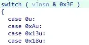
An assembly-based script can be pushed further to produce similar output, but working on Microcode is much more comfortable, because Microcode has already parsed and summarized the jump table:
jtbl (v18.1{8} & #0x3F.1), {0,0xA,0x13,0x18,0x1D,0x39,0x3B,0x3D => 9, 2 => 39, 7,0x33,0x34,0x3F => 17, 0xB => 40, 0xC,0x37 => 25, 0xE => 47, 0xF,0x1A,0x1E,0x20,0x21,0x26,0x28,0x2A,0x2B,0x2D,0x2E,0x31,0x35 => 7, 0x11,0x15,0x25,0x32 => 21, 0x14,0x17,0x1B,0x23,0x24,0x30,0x36,0x3A => 15, 0x19 => 52, 0x29 => 62, 0x38 => 68, def => 432} ; 2D3C u=w12.1A Microcode-based script:
# m_jtbl l, r=mcases
if minsn.opcode == ida_hexrays.m_jtbl :
    mcases = minsn.r.c
    casesvec = mcases.values
    targetvec = mcases.targets

    print(f'{i:3d}: 0x{minsn.ea:X} [switch]')
    for j in range(casesvec.size()):
        cases = casesvec.at(j)
        if cases.size() == 0 : continue
        cases_str = ", ".join(f"{cases.at(k)}" for k in range(cases.size()))
        target = targetvec.at(j)
        target_mblock = mba.get_mblock(target)
        print(f'{target:3d}: 0x{target_mblock.start:X} <- case : {cases_str}')

# output
#   6: 0x2D3C [switch]
#   9: 0x2DC0 <- case : 0, 10, 19, 24, 29, 57, 59, 61
#  39: 0x305C <- case : 2
#  17: 0x2ECC <- case : 7, 51, 52, 63
#  40: 0x3098 <- case : 11
#  25: 0x2F80 <- case : 12, 55
#  47: 0x30E8 <- case : 14
#   7: 0x2D40 <- case : 15, 26, 30, 32, 33, 38, 40, 42, 43, 45, 46, 49, 53
#  21: 0x2F24 <- case : 17, 21, 37, 50
#  15: 0x2E50 <- case : 20, 23, 27, 35, 36, 48, 54, 58
#  52: 0x312C <- case : 25
#  62: 0x3220 <- case : 41
#  68: 0x3254 <- case : 56
It’s exactly that compiler grouping that forces a second dispatch after the aggregated cases:
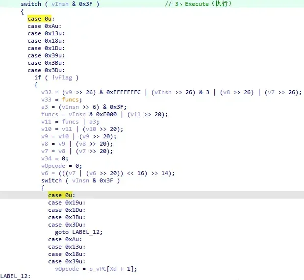
To analyze the complete execution of a single virtual instruction, there are three approaches:
- Work from IDA’s pseudocode and follow it by eye — but at function level it’s large and easy to get lost.
- Trace execution to get the list of real assembly instructions and walk them one by one — but at assembly level that’s a lot of work.
- Analyze at basic-block level, which sits comfortably in between. Concretely: write a Microcode simulator that simulates Microcode execution to recover the basic-block transition graph. The D-810 Microcode simulator is a good reference: https://gitlab.com/eshard/d810/-/blob/master/d810/emulator.py
Taking the first virtual instruction’s opcode — 21 (0x15):
simulator output:
opcode=21 : 21-0x2F24, 22-0x2F54, 38-0x3048

analysis:
1. 21-0x2F24
(1) assembly:
; jumptable 0000000000002D3C cases 17,21,37,50
0x2F24 AND W0, W12, #0xF000

(2) pseudocode:
case 0x15u:
  imm16 = vInsn & 0xF000 ...

2. 22-0x2F54
(1) assembly:
0x2F54 CMP W11, #0x15

(2) pseudocode:
if ( vOpcode == 0x25 || vOpcode == 0x15 )

3. 38-0x3048
(1) assembly:
0x3048 ADD X11, X21, #8        ; X11 = X21 + 8
0x304C LDR X9, [X11,W9,UXTW#3] ; X9 = *(X11 + (W9 << 3))
0x3050 ADD X9, X9, W10,SXTH    ; X9 = X9 + X10 = X9 + imm16
0x3054 STR X9, [X11,W8,UXTW#3] ; *(X11 + (W8 << 3)) = X9

equivalent to: *(X11 + (W8 << 3)) = *(X11 + (W9 << 3)) + imm16

(2) pseudocode:
*(v12 - 0x130 + 8LL * v29) = *(v12 - 0x130 + 8LL * v28) + v44;
As noted earlier, ARM computes through registers, which means:
1. This is an add-immediate instruction
2. v12 - 0x130 + 8LL * v29  corresponds to the virtual destination register: vXd
3. v12 - 0x130 + 8LL * v28  corresponds to the virtual source register:     vXn
From that we can deduce:
1. v12 - 0x130 corresponds to the first virtual register: vX0
2. v29 = W8[4:0]  = W12[20:16]  is the virtual destination register number
3. v28 = W9[4:0]  = W12[25:21]  is the virtual source register number
So the virtual opcode’s format is:
vADD vXd, vXn, #immPlugging in the concrete data gives the meaning of the first virtual instruction:
│31│30-26│25-21│20-16│15-12│11-6│5-0│
│ 1│   23│   29│   29│   15│   48│ 21│

W8[4:0]  = W12[20:16] = 29
W9[4:0]  = W12[25:21] = 29

vADD vX29, vX29, -0x210
5.4 PCUpdate
After a virtual instruction executes, the next step is advancing:
0x3058: B def_2D3C ; branch to the PC-update basic block

0x3A78 def_2D3C
0x3A78 LDR X9, [X21]          ; vPCOld = *p_vPC
0x3A80 ADD X0, X9, #4         ; vPC = vPCOld + 4 -> vPC = *p_vPC + 4
0x3A88 STR X0, [X21]          ; *p_vPC = vPC;
Here vPC advances by 4 — i.e. sequential execution. But execution can also branch, or even call out to an external function. So the remaining cases are branches and external calls:
v91 = *(v12 - 0x20);   // v12 - 0x20: flag, decides sequential vs. branch
if ( v91 == 2 )
    if ( !vPC ) return vPC;
    goto fetch;        // jump back to Fetch

if ( v91 == 3 || v91 == 1 )
    vPC = *(v12 - 0x18);        // v12 - 0x18: branch or call address
    *(v12 - 0x20) = 0;          // clear flag
    if ( vPC == v13 )           // v13: trampoline, used to call external functions
        (v13)(*v15, *v16);      // call external function
        vPC = *(v12 - 0x10);    // v12 - 0x10: return address after the call
        if ( !vPC ) return vPC;
        goto fetch;             // jump back to Fetch
    else                        // vPC != v13, not a trampoline
        if ( !vPC ) return vPC;
        goto fetch;             // jump back to Fetch
After PCUpdate comes the next Fetch, and there’s a detail worth noting:
# right after fetch, the state gets a small tweak
vInsn = *vPC;          // 1. Fetch
if ( flag == 2 ) {     // flag == 2 gets bumped to flag == 3
    flag = 3;
    *(v12 - 0x20) = 3;
}
Which means: if some instruction sets flag == 2, then on the next instruction:
- at the start of that next instruction: because
flag == 2, it becomesflag = 3 - at the end of that next instruction: because
flag == 3, it branches
As an example, following the virtual code’s order it should be 00000078 first and then 0000007C. But with this special scheduling, the effective behavior becomes 0000007C first, then 00000078:
0000007C 02400017 : STR  X0, [X18, #0x0]
00000078 08000A8C : BR   #0x2A8
6. The virtual machine’s state
Earlier I said the virtual machine must provide virtual registers for virtual instructions to compute with. From the execution loop we can also see that the virtual machine depends on a few special variables playing special roles. The VM state (VMState) is exactly this bundle of virtual registers plus those special variables — the context a virtual instruction runs against.
From the analysis so far:
v12 - 0x130 : vX0
v12 - 0x20  : flag
v12 - 0x18  : branch or call address
v12 - 0x10  : return function after a call
From vX0 we can extrapolate the other general-purpose registers:
0x2C38 SUB  X8, X19, #0x130    ; X19 - 0x130 -> v12 - 0x130 : vX0
0x2C3C STUR XZR, [X19,#-0x38]  ; X19 - 0x38
0x2C40 STR  XZR, [X8]

; (0x130 - 0x38) / 8 = 0x1F = 31, i.e. vX0 through vX31
Fleshing out the VMState from more virtual instructions gives the full structure:
00000000 struct VMState // sizeof=0x150
00000000 {
00000000     uint64_t vStack;
00000008     uint64_t vStack1;
00000010     uint64_t _pad0;
00000018     uint64_t vPC;
00000020     uint64_t vX0;
00000028     uint64_t vX1;
00000030     uint64_t vX2;
00000038     uint64_t vX3;
00000040     uint64_t vX4;
00000048     uint64_t vX5;
00000050     uint64_t vX6;
00000058     uint64_t vX7;
00000060     uint64_t vX8;
00000068     uint64_t vX9;
00000070     uint64_t vX10;
00000078     uint64_t vX11;
00000080     uint64_t vX12;
00000088     uint64_t vX13;
00000090     uint64_t vX14;
00000098     uint64_t vX15;
000000A0     uint64_t vX16;
000000A8     uint64_t vX17;
000000B0     uint64_t vX18;
000000B8     uint64_t vX19;
000000C0     uint64_t vX20;
000000C8     uint64_t vX21;
000000D0     uint64_t vX22;
000000D8     uint64_t vX23;
000000E0     uint64_t vX24;
000000E8     uint64_t vX25;
000000F0     uint64_t vX26;
000000F8     uint64_t vX27;
00000100     uint64_t vX28;
00000108     uint64_t vX29;
00000110     uint64_t vX30;
00000118     uint64_t vX31;
00000120     uint64_t _pad1;
00000128     uint64_t _pad2;
00000130     uint64_t vFlag;
00000138     uint64_t vAddrJump;
00000140     uint64_t vAddrReturn;
00000148     uint64_t vAddrBase;
00000150 };
A note on the members. v12 - 0x20 is flag, and its offset is negative (-0x20). IDA structures don’t support negative offsets, so to express it with a positive offset you index from element -1:
v12 - 0x20 : flag
flag's offset is negative: -0x20

IDA structs don't support negative offsets,
so switch to element -1 to get a positive offset:

normally:   VMState + flagOffset        = &VMState[0] + flagOffset
change to:  &VMState[-1] + sizeof(VMState) + flagOffset
concretely: sizeof(VMState) is 0x150, flagOffset is -0x20
so:         0x150 - 0x20 = 0x130 -> 00000130 uint64_t vFlag;
Replacing v12 with VMState * makes the virtual instructions far more readable in IDA:
1st virtual instruction, pseudocode:
*(v12 - 0x130 + 8LL * v29) = *(v12 - 0x130 + 8LL * v28) + v44;

with VMState it becomes much clearer:
*(&VMState[-1].vX0 + Xd) = *(&VMState[-1].vX0 + Xn) + imm16;
7. Conclusion
VMP virtualization transforms real code into virtual code plus a virtual machine, and the virtual machine runs that virtual code by its own rules to reproduce the real code’s behavior.
As for code protection — its purpose is really to raise the cost of reverse engineering. VMP’s design has two key points:
1. Redefine the format/meaning of virtual instructions
2. Re-arrange how the virtual machine executes
Correspondingly, reversing VMP requires nailing down two things:
1. Reconstruct how the virtual machine executes
2. Recover the format/meaning of the virtual instructions
8. Postscript
Some time ago I was planning to harden an Android .so and found that VMProtect didn’t support Android’s ARM64. On the commercial side there are a few Android .so packers, but they’re expensive. On the open-source side there’s xVMP, but it’s only a demo. Porting VMProtect’s virtualization strategy into xVMP would be a massive amount of work.
Then I came across a very thorough public VMP analysis — the sample being a mature, production-grade scheme from a major vendor, which makes it ideal study material for writing a complete xVMP of my own.
And on October 1st, VMProtect added ARM64 support for Android…
Colin Xiao — I take on contract reverse-engineering work, and writeups like this are how I show what I can do. If you need help with anything in this space — including but not limited to the areas I cover above — I’m available. No project is too big or too small — if it’s reverse engineering and I can do it, I’ll take it. DM me on X (@colinxiao_lab) or Telegram (@ColinXiao666).
Get in touch